


The lattice feature adds extra edges to your design to make it appear that some lines go over and under other lines. The extra edges are called “lattice edges”. You can set the color and width of these lines independently from the width and color of the design edges. They are separate from the design edges. (This allows you to still use the designs edges to cut out your design.)
In Polygonia, when two lines join each other, by crossing each other or connecting to each other, they combine and form a corner or a straight line. This is how Polygonia normally works (that is, when the lattice feature is not turned on). The lattice feature introduces the concept of levels. You tell Polygonia which lines go over or under other lines. By default all lines are on the same level, which is 0 (zero). When you enable the lattice feature you have the option of changing the level of parts of one or more lines. The lattice feature distinguishes between the start, the middle, and the end of the line.
There are three steps to create a lattice:
- Enable the lattice feature
- Change the level of a line or endpoint
- (Optionally) Set the level behavior
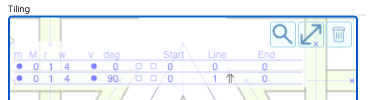
These settings are in the Tiling tab (the tab with the tile editor). The lattice edge color and line width settings are in Lines tab, in the “Lattice Line” panel.
Enable Lattice
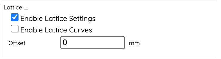
Click on the “Lattice . . . “ label to expand the panel. Check the “Enable Lattice Settings” box.
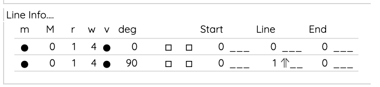
Nothing will change when you first enable the lattice feature, because everything is still on level zero. When you enable the lattice feature, six columns are added to the line info table (both in the editor and in the “Line Info” panel). The columns are
- Start point level
- Start point level behavior
- Line level
- Line level behavior
- End point level
- End point level behavior
These are explained below.
Change the level
The next step is to change the level of the start, middle, or end of one or more of the lines. The middle of the line is everything between the start and end, but not including the start and end. It helps to thing of a piece of string: you can hold up the start and end of the string at the same height, but everything in between will be a little lower — this is why the user interface uses “Line” instead of “Middle”. The display shows “Start”, “Line”, and “End” over the six columns.
Which value should you change? If two lines cross in the middle of each other, then you would change the level of middle of just one of the lines. You change the level by placing your cursor over the number in the start, line, or end column and pressing the up or down arrow.
Set the behavior
The lines you draw in the editor are reflected (mirrored), rotated, and translated (moved) to create your design. When you first set a level for part of a line (start, middle, or end), it stays at the level for the entire design. This might be exactly what you want. But you can also have the level change, alternate from above (positive level) to below (negative level). You can change the behavior of the level, that is, have the level change from above to below or below to above, when the line reflects, rotates, or translates, or any combination of the three.
Next to the height field is the “behavior” field. Initially it is blank, meaning that the level does not alternate. Using the up/down arrow you can go through all combinations of “alternate on reflection”, “alternate on rotation”, and “alternate on translation (adjacent tile)”. Arrow symbols indicate which behaviors are applied.
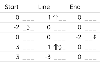
⇑ : Alternate on reflection
⤸ : Alternate on rotation
↕ : Alternate on translation
The “alternate on translation” applies to adjacent tiles, but only for square tilings and triangles tilings.
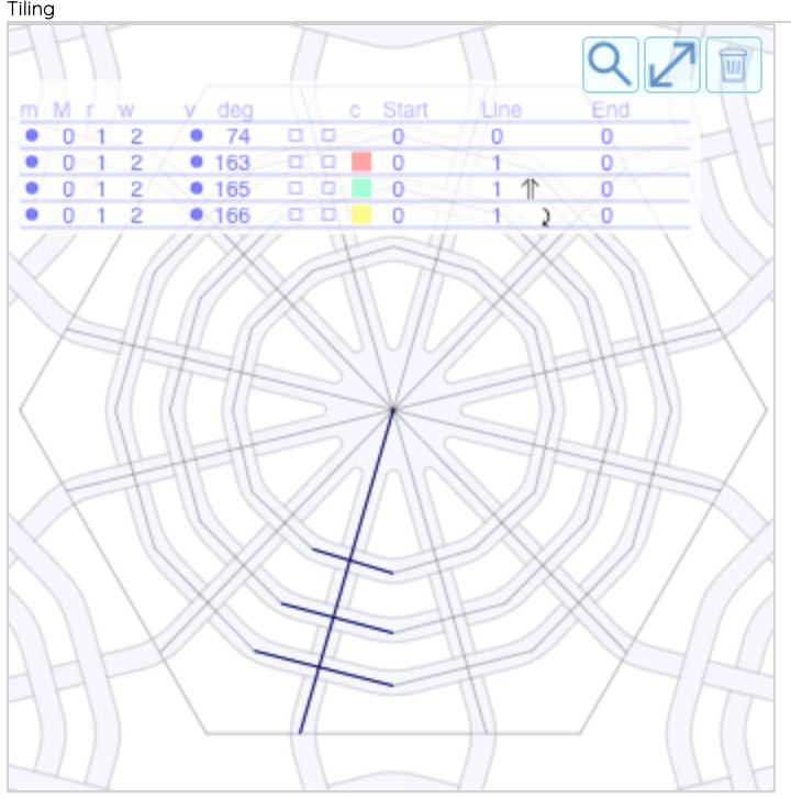
Here is a screen shot of the line info table. The first row shows a level 1 for the middle of a line and that it alternates on reflection. The second rows shows that the start of the line has level -2 and it alternates on reflection. The third rows shows that the end of the line has level -2 and it alternates on translation (for adjacent tiles). The fourth row shows a level of 1 for the middle of the line and that it alternates on both reflection and rotation and a level of 3 for the start of the line that does not alternate.
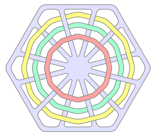
Here is a comparison no alternating behavior, alternate on reflection, and alternate on rotation. Below is a design with four lines on a hexagon tile. The first line starts at the center and goes to the edge. It has level 0, the default. The other three lines have a level of 1. The red line’s level stays at 1, so it appears always over the blue lines. The green line’s level alternates on reflection, so it start over (level 1), and then goes under the next line (it alternates to -1), then it repeats, going over and under. The yellow line’s behavior alternates on rotation. The original line and its reflection are both level 1, so it goes over two lines. Then the first rotation alternates the level, to -1, so it goes under two lines, and then it repeats.
Examples
Two Lines Crossing
Here is an example using two lines in a triangle tiling. The first image shows the original design without lattice enabled. The remaining images show the lattice feature, with changing only the level and behavior of the line that makes the triangle in the design. I am using color to help see the lattice.
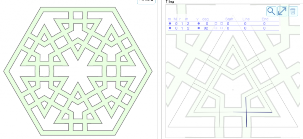
Two Lines at the same level 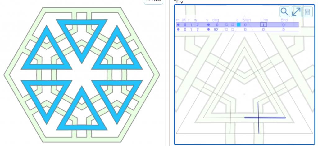
One line has level that stays at 1 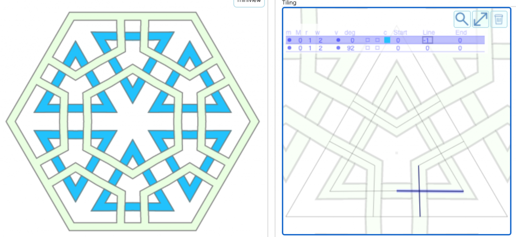
One line has level that stays at -1 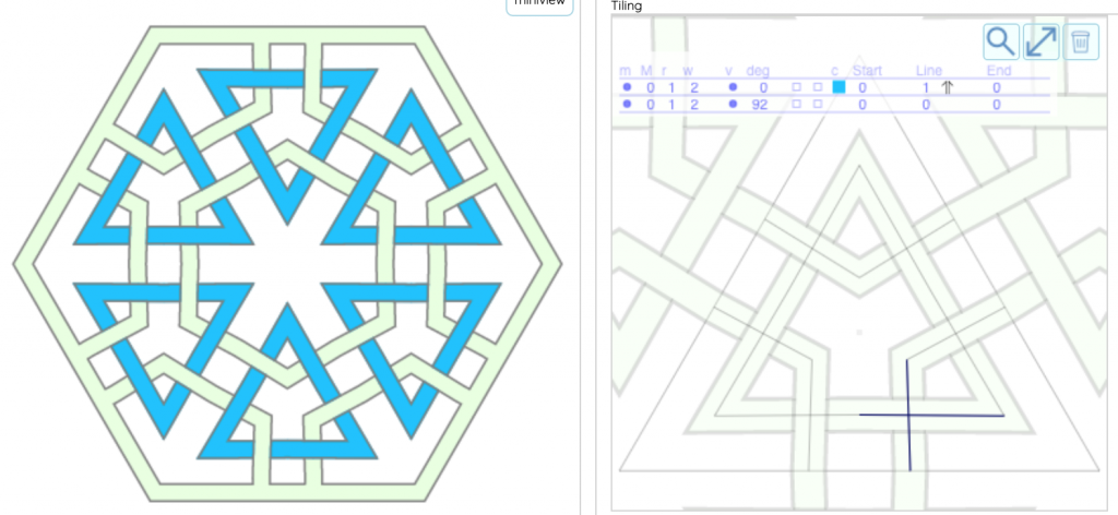
One line has level 1, alternate on reflection 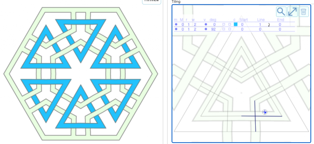
One line has level 1, alternate on rotation 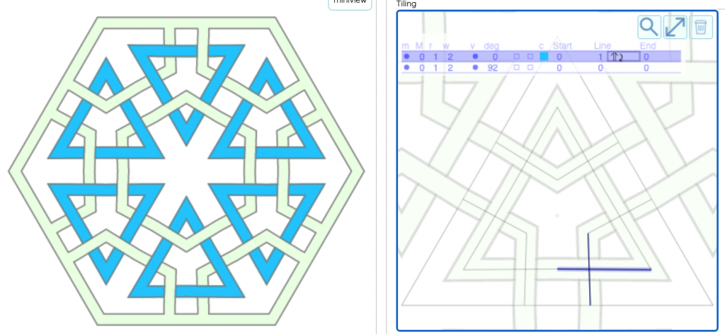
Alternate on reflection and rotation 
Alternate on translation 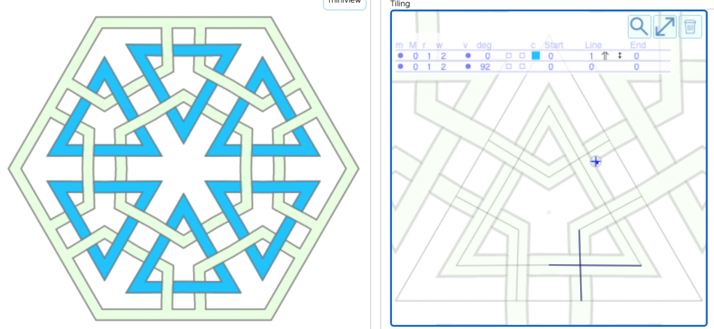
Alternate on reflection and translation
Endpoint and a Line
Here are examples shows two lines on a square tiling. In this case one line (making the square) has an endpoint on the other line.
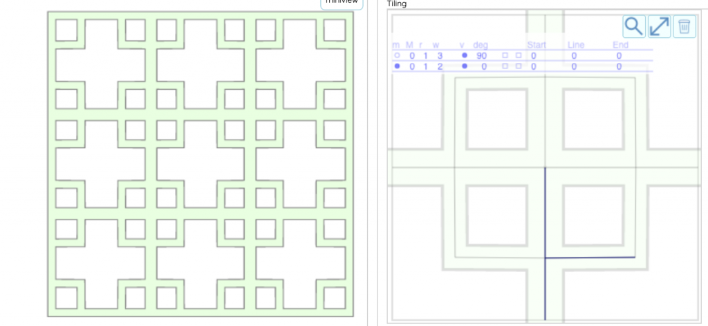
Everything at the same level 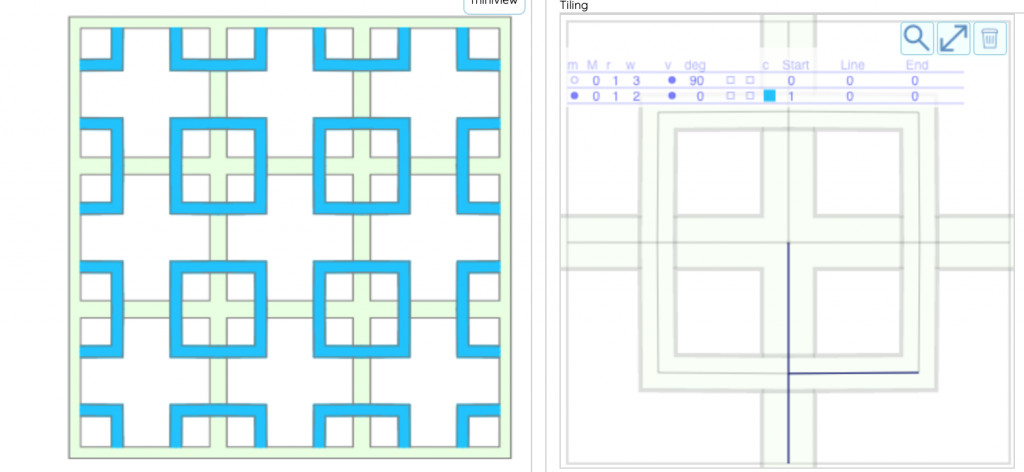
Endpoint of the line making the square is level=1 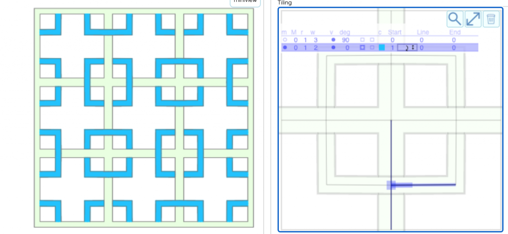
Endpoint is level=1, alternating on reflection and translation 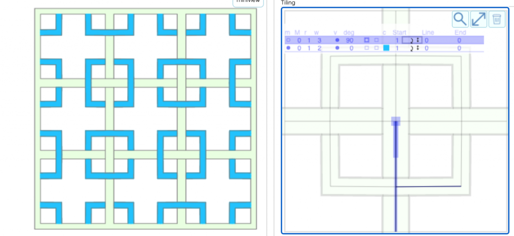
Endpoint is level=1, alternating on reflection and translation for both lines
Other Settings in the “Lattice” panel
Lattice Curves
The “Enable Lattice Curves” setting tells Polygonia to use curve when drawing the lattice edges. When this setting is off, Polygonia will make corner, even if curves are enabled for the design. When this setting is on, Polygonia will use the curve setting for the design. If curves are not enabled for the design, then this setting will have no effect.
Lattice Offset
The “Offset” field in the “Lattice” panel tells Polygonia to shift the lattice edge towards (positive) or away from (negative) the design edge. If you are using your design with on a paper cutter or laser cutter, then this feature will allow you to adjust the alignment of the pen (if you a pen on a paper cutter) or the location of the etching (if using a laser cutter).
“Lattice Line” Settings in the “Lines” tab
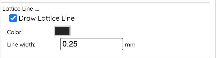
The “Draw Lattice Line” checkbox controls whether or not the lattice edge is rendered.